Read Engineering Drawings and Tolerances

Original Dimensioned Diagrams

Three original vector drawings built for this course: precise teaching figures, not decorative or AI-generated art. Zoom or print each one; the underlying numbers match the worked examples in the chapters and worksheets exactly.

M9-ED-001

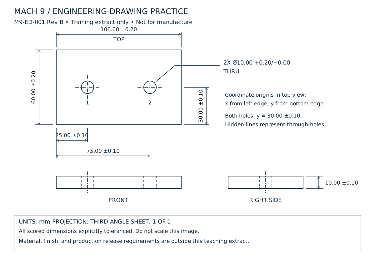
Two-hole plate drawing

Download SVG
Third-angle top, front and right-side views of the 100 × 60 × 10 mm training plate, dimensioned exactly as worked through in Chapters 1–3 and Worksheets W01–W04.
M9-ED-002

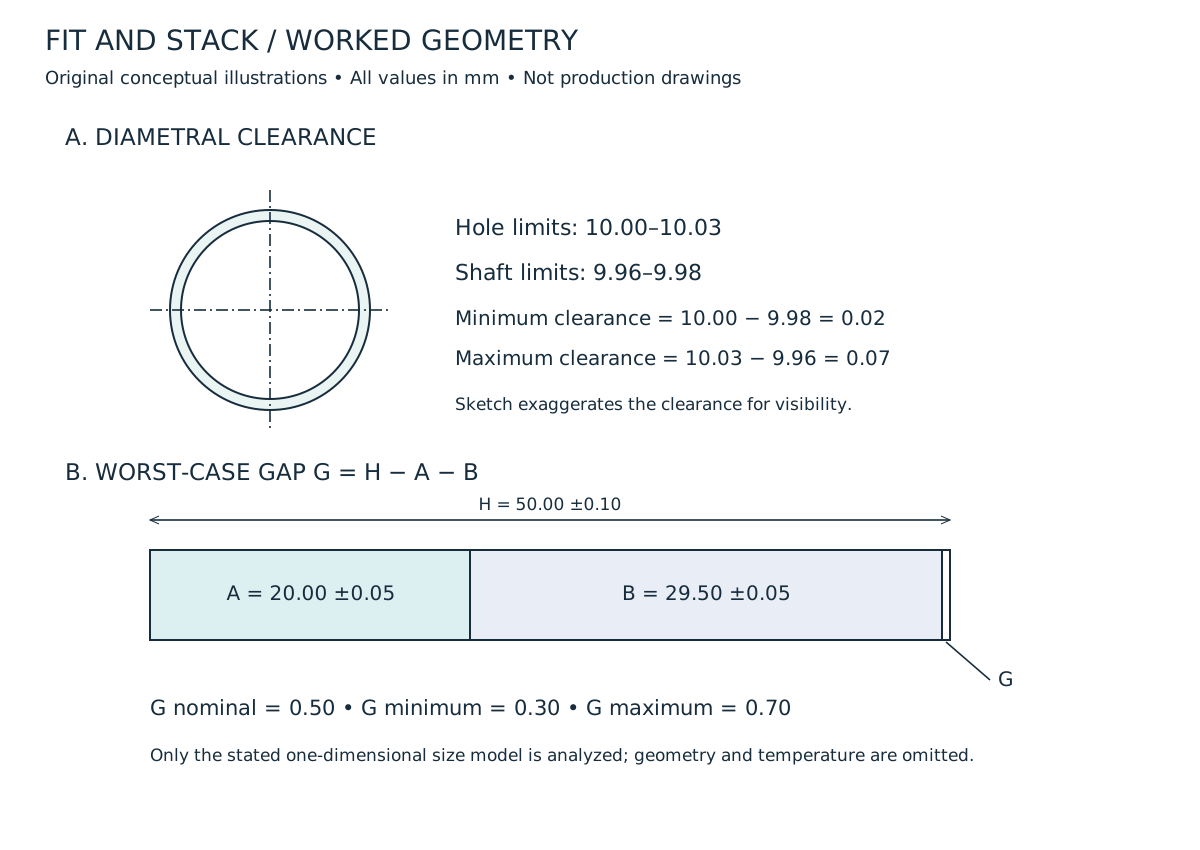
Fits and worst-case gap

Download SVG
Two concentric circles illustrate a hole-and-shaft fit; a housing span containing two spacers and a gap illustrates the worst-case stack-up worked in Chapter 3.
M9-ED-003

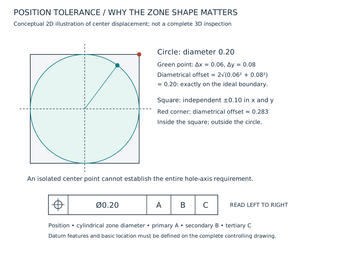
Position circle compared with coordinate square
Download SVG
A diameter-0.20 position circle and a ±0.10 coordinate square share a center: the Δx = 0.06, Δy = 0.08 offset sits on the circle, while the 0.10/0.10 corner of the square sits outside it, the comparison worked in Chapter 4.

← Back to Read Engineering Drawings and Tolerances